

Views: 0 Author: Site Editor Publish Time: 2026-08-16 Origin: Site


A pneumatic actuated valve uses compressed air to open, close, or regulate flow and is widely used in industrial automation systems. Choosing the right valve requires considering factors such as media, pressure, temperature, flow rate, actuator type, air supply, materials, and fail-safe requirements. This guide explains the main pneumatic valve types, key selection factors, actuator options, application considerations, common mistakes, and the information needed for proper valve selection.
What Is a Pneumatic Actuated Valve?
How Does a Pneumatic Actuated Valve Work?
Types of Pneumatic Actuated Valves for Flow Control
Key Factors When Selecting a Pneumatic Actuated Valve
Double-Acting vs. Spring-Return Pneumatic Actuators
How to Choose the Right Valve for Different Applications
Common Mistakes When Selecting Pneumatic Actuated Valves
What Information Should You Provide Before Valve Selection?
FAQ
Core Keywords: Pneumatic Actuated Valve,Pneumatic Actuated Ball Valve,Pneumatic Actuated Butterfly Valve,Pneumatic Control Valve,Pneumatic Actuator,Pneumatic On-Off Valve
A pneumatic actuated valve is an automated valve assembly that uses compressed air to move the valve between specified positions. The complete assembly normally includes a valve body, pneumatic actuator, mounting kit, and control or feedback accessories. Depending on the process, it may operate as a fully open/fully closed isolation valve or as a modulating valve that adjusts flow continuously.
Pneumatic actuation is widely used in industrial systems because it offers fast operation, a relatively simple mechanical design, and practical integration with plant control systems. A solenoid valve can direct air for on-off operation, while limit switches send open and closed position feedback to a PLC or distributed control system. For proportional control, an electro-pneumatic positioner adjusts valve position in response to a control signal.
A pneumatic actuated valve should be treated as a complete engineered assembly, not as a valve body and actuator selected independently. The valve torque, actuator output, available air pressure, mounting interface, accessories, and intended fail position must all be compatible.

Compressed instrument air enters one or more actuator chambers and moves internal pistons or a diaphragm. In a common rack-and-pinion rotary actuator, piston movement turns a pinion connected to the valve stem. This rotation opens or closes a ball valve or butterfly valve, typically through a quarter turn. Linear pneumatic actuators move the stem of globe-style control valves up or down.
The actuator may use air in both directions or air in one direction with springs providing the return stroke. A double-acting actuator receives air alternately at two ports to open and close the valve. A spring-return actuator uses air for one direction and stored spring force for the other, allowing the valve to move to a predetermined safe position if the air supply is lost.
Accessories define how the assembly interacts with the process:
A solenoid valve switches the air path for on-off control.
A limit switch box confirms valve position remotely.
A positioner converts a control signal, often 4–20 mA, into controlled actuator movement.
A filter regulator helps provide clean air at a stable operating pressure.
A speed controller adjusts opening and closing speed where rapid movement could cause water hammer or process disturbance.
Reliable operation depends on adequate actuator torque at the minimum air pressure available at the actual installation point. Compressor discharge pressure alone does not show what the actuator will receive during peak plant demand.
The correct valve type depends on whether the task is isolation or throttling, as well as the media, line size, allowable pressure drop, leakage requirement, and space available. The following table summarizes the three common options.
| Valve Type | Typical Function | Main Advantages | Important Selection Considerations |
|---|---|---|---|
| Pneumatic Ball Valve | On-off isolation; limited or characterized modulation | High flow capacity, tight shutoff, low pressure loss in full-port designs | Higher torque and weight at large sizes; standard round-port balls are not ideal for precise throttling |
| Pneumatic Butterfly Valve | Isolation or moderate flow regulation, especially in larger pipes | Compact, lightweight, economical in large diameters | Disc remains in the flow path; confirm pressure drop, seat rating, cavitation risk, and media compatibility |
| Pneumatic Control Valve | Continuous modulation of flow, pressure, level, or temperature | Better control characteristics and positioning accuracy | Requires correct Cv sizing, actuator sizing, trim selection, and a suitable positioner |
A pneumatic ball valve uses a rotating ball with a bore through its center. When the bore aligns with the pipeline, fluid passes through; when the ball rotates 90 degrees, the flow is shut off. Full-port ball valves provide a relatively unobstructed flow path and low pressure loss, making them useful for isolation duties involving clean liquids, gases, and some viscous media.
Ball valves generally provide strong shutoff performance, but their breakaway torque can be significant because the seats remain in contact with the ball. Torque may increase with differential pressure, long periods without cycling, deposit buildup, or temperature changes. The actuator must be sized from the valve manufacturer's torque data for the actual service conditions, with an appropriate safety margin.
Standard ball valves should not automatically be used for precise throttling. If proportional control is required, a V-port ball or another characterized design may provide a more predictable flow curve than a conventional round-port ball.
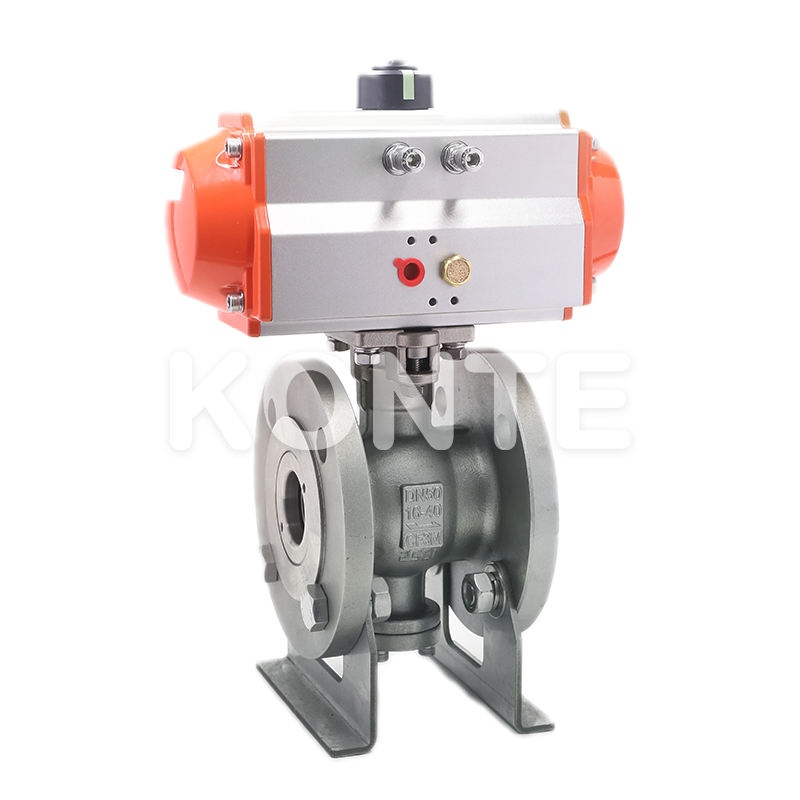
A pneumatic butterfly valve controls flow with a disc mounted on a rotating shaft. Its narrow face-to-face dimension, low weight, and relatively modest actuator requirement often make it practical for medium and large pipe sizes. Common applications include water, cooling systems, compressed air, and other compatible utility services.
Because the disc remains in the flow path, a butterfly valve produces some obstruction even when fully open. High differential pressure or unsuitable operating angles can increase vibration, noise, cavitation, and wear. Seat material, disc material, pressure class, and shutoff requirement must therefore be checked carefully.
Butterfly valves are often an efficient large-diameter solution, but they should be selected using actual flow and pressure-drop data rather than pipe size alone.
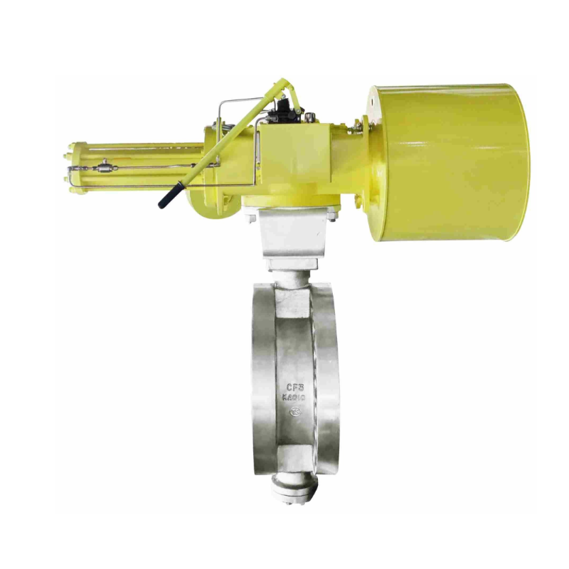
A pneumatic control valve changes its opening continuously to regulate flow, pressure, temperature, or liquid level. It normally uses a pneumatic actuator and a positioner that compares the requested control signal with the actual valve position. Globe control valves are common for accurate throttling, while characterized ball and butterfly valves can also serve modulating duties in suitable applications.
Control valve selection requires a calculated flow coefficient, or Cv, rather than a simple line-size match. An oversized valve may operate near the closed position, reducing control resolution and causing hunting. An undersized valve may restrict production and fail to deliver the required maximum flow.
For modulating service, control range and valve characteristics are as important as maximum flow capacity. Trim design, pressure recovery, noise, cavitation, flashing, and shutoff class may also influence the final choice.
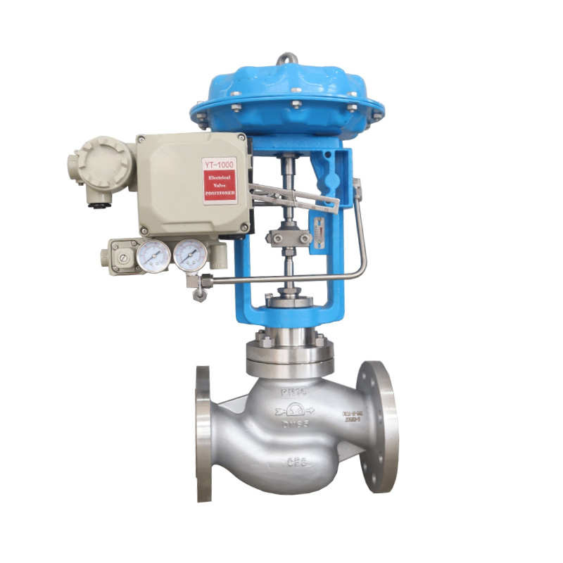
First identify whether the media is a liquid, gas, steam, slurry, powder-laden flow, or another process fluid. Record its chemical composition, concentration, viscosity, solids content, and potential for crystallization or buildup. Clean media may suit soft-seated valves, while abrasive particles can damage soft seats and sealing surfaces. Corrosive fluids require compatible body, trim, seat, stem, packing, and gasket materials.
Media behavior also affects torque and valve geometry. Viscous fluids may need a full-bore flow path, while fibrous or particulate media may collect around narrow cavities or the butterfly disc. Every wetted component must be checked for chemical, mechanical, and temperature compatibility with the process media.
Provide the minimum, normal, and maximum inlet and outlet pressures, not only the pipeline pressure class. The differential pressure across the closed or moving valve directly affects required torque and control performance. In throttling service, a high pressure drop may cause cavitation in liquids, flashing, excessive velocity, vibration, or aerodynamic noise in gases.
Temperature influences pressure rating, seat selection, packing, seals, actuator lubrication, and accessory performance. PTFE-based seats may be suitable for many general services, but high-temperature or abrasive duties can require engineered polymer, graphite, or metal-seated construction. Very low temperatures may require extended stems or specialized sealing.
Pressure and temperature must be evaluated together because a material's allowable pressure commonly decreases as temperature rises. Always use the relevant manufacturer's pressure-temperature rating for the selected construction.
For on-off service, line size is a useful starting point, but allowable pressure loss and required flow still need verification. For modulating service, calculate the required Cv using the media properties, flow range, inlet pressure, outlet pressure, and temperature. The normal operating point should fall within a controllable part of the valve travel rather than very close to fully closed or fully open.
Also check line velocity and the effect of reducers if the selected valve is smaller than the pipe. A correctly sized valve provides the required flow while maintaining stable control, acceptable velocity, and manageable pressure drop.
Select rotary or linear motion to match the valve. Rack-and-pinion rotary actuators provide a compact, generally consistent torque profile for many ball and butterfly valves. Scotch-yoke actuators provide higher torque near the beginning and end of the stroke and may suit valves with high breakaway and seating torque. Linear diaphragm or piston actuators are commonly paired with globe control valves.
Actuator output must exceed the valve's required torque or thrust throughout the complete stroke. Use the minimum guaranteed instrument-air pressure, not the highest compressor pressure. Apply an appropriate design margin to account for seat friction, aging, deposits, dry gas, infrequent cycling, and process variation. A typical project may use a 20–30% margin, but severe or uncertain service can require a larger margin based on engineering review.
Never estimate actuator size from valve diameter alone; use the valve torque or thrust data and the actuator output at the minimum available air pressure.
Common body materials include ductile iron, carbon steel, stainless steel, and engineered plastics. Seats and seals may use EPDM, NBR, PTFE, reinforced PTFE, PEEK, graphite, elastomers, or metal constructions. The correct combination depends on corrosion, temperature, abrasion, sanitation, leakage limits, and cleaning requirements.
Connections may be threaded, flanged, wafer, lug, socket-weld, butt-weld, clamp, or another project-specific standard. Confirm nominal size, pressure class, flange standard, face-to-face dimension, and pipe schedule. ISO 5211 valve-to-actuator mounting interfaces and standardized accessory mounting can simplify assembly and future replacement, but the stem dimensions and torque capacity must still match.
Material and connection specifications must cover both process compatibility and mechanical installation requirements.
The fail-state requirement is the main distinction between these two actuator designs.
| Selection Point | Double-Acting Actuator | Spring-Return Actuator |
| Operating method | Air opens and air closes | Air moves one way; springs return the valve |
| Air-loss response | Usually remains in its last position, subject to process forces and system design | Moves to a defined fail-open or fail-closed position |
| Air consumption | Uses air in both directions | Uses air for one direction |
| Size and cost | Often smaller and more economical for the same valve duty | Often larger because spring force must also be overcome |
| Typical use | General automation where fail-in-place is acceptable | Safety-related isolation, venting, cooling, or shutdown duties |
A double-acting actuator is suitable where compressed air is dependable and process risk analysis permits the valve to remain in its last position after air loss. It can offer a compact solution and strong torque in both directions.
A spring-return actuator is selected when the valve must move automatically to a safe state. Fail-closed action may isolate fuel or hazardous chemical flow. Fail-open action may maintain cooling water or open a depressurization path, depending on the process design. The correct fail state must come from a formal process and safety assessment.
Choose the actuator configuration according to the required air-failure position, not merely initial cost or available space. Spring-return sizing must confirm adequate spring-end torque as well as adequate air-stroke torque at minimum supply pressure.

Water treatment systems use actuated valves for intake, filtration, chemical dosing, backwashing, sludge handling, and distribution. Butterfly valves are often practical for larger clean-water lines, while ball valves may suit smaller isolation or dosing lines. Sludge and suspended solids require attention to blockage, abrasion, and seat wear.
Materials must match water chemistry and any treatment chemicals. Opening and closing speed should be controlled where rapid movement could produce water hammer. For water treatment, prioritize corrosion resistance, suitable sealing, manageable pressure loss, and reliable cycling.
Chemical service begins with a detailed compatibility review covering the body, seats, seals, stem, packing, and gaskets. Chemical concentration and temperature can change material resistance significantly. Toxic, flammable, or highly corrosive service may require low-emission packing, fire-safe construction, cavity relief, or a defined fail-safe position, depending on applicable standards and plant requirements.
Do not select a chemical-service valve from a generic material label alone; evaluate the exact chemical, concentration, temperature, and operating conditions.
Oil and gas applications may involve high pressure, hydrocarbons, sour service, combustible atmospheres, and strict shutdown requirements. Ball valves are commonly considered for tight isolation and high-flow pipelines, while control valves are used for pressure and flow regulation. The valve pressure class, fire-safe requirements, leakage standard, antistatic features, material traceability, and hazardous-area rating of electrical accessories must be specified where applicable.
Spring-return actuators are frequently used in emergency shutdown functions, but the fail position depends on the process hazard analysis. Oil and gas valve selection must align mechanical performance, environmental classification, and the facility's safety philosophy.
Food and beverage systems require materials and internal surfaces compatible with the product and cleaning process. Hygienic connections, drainable geometry, suitable elastomers, and clean-in-place or sterilize-in-place conditions may be important. The maximum cleaning temperature and cleaning chemicals can be more demanding than normal production conditions.
Wash-down exposure also affects the enclosure and corrosion resistance of solenoids, switch boxes, and positioners. For hygienic applications, evaluate cleanability and sanitation requirements for the complete actuated assembly, including accessories.
General industrial automation includes compressed air, cooling water, steam, vacuum, utility gases, machine skids, and production lines. The first decision is whether the valve provides on-off isolation or continuous modulation. On-off assemblies typically use a solenoid and position feedback, while modulating assemblies require a compatible positioner and suitable valve characteristic.
Cycle frequency, required response time, ambient dust or moisture, vibration, maintenance access, and communication with the PLC or DCS should all be considered. A standardized mounting and accessory arrangement can reduce spare-parts complexity and simplify maintenance across a plant.
Several recurring errors reduce reliability or create unsafe operation:
Selecting by pipe size only. This ignores Cv, velocity, pressure drop, shutoff needs, and control range.
Using compressor maximum pressure for actuator sizing. Actual pressure at the valve can be much lower during peak demand.
Ignoring breakaway and seating torque. These values can be higher than running torque and may increase after long idle periods.
Applying too little design margin. Wear, deposits, dry media, and infrequent cycling can increase torque over time.
Choosing the wrong fail position. Fail-open, fail-closed, or fail-in-place must follow the process safety assessment.
Using an on-off valve for precise modulation. A standard ball or butterfly valve may not provide the required flow characteristic.
Checking body material but not soft parts. Seats, seals, packing, and gaskets are often the first components affected by chemical or temperature incompatibility.
Ignoring instrument-air quality. Moisture, oil, and particles can damage actuator seals and pneumatic accessories.
Omitting ambient conditions. Corrosive air, wash-down, outdoor exposure, low temperature, or hazardous areas affect housing, coating, and electrical accessory selection.
Failing to verify mounting compatibility. The coupling, stem, bracket, mounting pattern, and rotation direction must be checked as an assembly.
The most reliable selection process verifies the valve, actuator, air system, controls, and installation environment together.
Providing a complete process data sheet allows a valve supplier or application engineer to size and configure the assembly accurately. At minimum, provide:
Media name, composition, concentration, state, viscosity, density, and solids content
Minimum, normal, and maximum flow rate
Minimum, normal, and maximum inlet pressure
Outlet pressure or maximum differential pressure
Minimum, normal, and maximum process temperature
Pipe size, schedule, connection type, flange standard, and pressure class
Required function: on-off isolation, emergency shutdown, or modulation
Required shutoff or leakage class
Normal valve position and required failure position
Minimum and maximum instrument-air pressure at the valve
Available electrical power and control signal
Required opening or closing time and cycling frequency
Body, trim, seat, and seal material preferences or restrictions
Indoor/outdoor location, ambient temperature, corrosion, wash-down, dust, vibration, and hazardous-area requirements
Required standards, certificates, inspection, testing, or documentation
Space, orientation, manual override, and maintenance-access limitations
For a control valve, also provide the desired control range, allowable pressure drop, and information needed to calculate Cv. For safety-related service, state the applicable shutdown logic and performance requirements. Complete and accurate operating data reduces oversizing, undersizing, compatibility errors, and unnecessary project revisions.
Start with the valve manufacturer's breakaway, running, and seating torque—or thrust for a linear valve—at the maximum differential pressure. Apply an appropriate design margin, then compare the result with actuator output across the full stroke at the minimum guaranteed air pressure at the installation point. For spring-return units, verify both the air stroke and spring stroke.
A pneumatic on-off valve normally operates only in fully open and fully closed positions and commonly uses a solenoid valve. A pneumatic control valve moves proportionally to regulate a process variable and normally uses a positioner. The valve trim or port geometry must also be suitable for stable modulation.
Possible causes include inadequate air pressure, an undersized actuator, debris on the seat, incorrect travel-stop adjustment, worn seals, stem or disc binding, a faulty solenoid, or excessive differential pressure. The correct diagnosis should compare the available actuator torque with the valve's actual seating requirement and inspect the mechanical and pneumatic components.
Choose based on the service rather than a universal rule. A ball valve is often preferred for tight isolation, high flow capacity, and low pressure loss in smaller or medium sizes. A butterfly valve is often compact and economical for larger lines. Media, pressure, temperature, torque, shutoff, Cv, installation space, and life-cycle cost should determine the final choice.
Yes. A suitable valve body, actuator, and positioner can provide modulating control. Globe valves, V-port ball valves, and characterized butterfly valves are common options. Correct Cv sizing and a suitable inherent flow characteristic are necessary for stable performance.
The actuator and accessories should receive clean, dry air at the pressure specified by their manufacturers. Filtration and regulation are commonly used to limit particles, moisture, and oil contamination. Poor instrument-air quality can shorten seal life, obstruct small pneumatic passages, and cause unreliable valve movement.
ISO 5211 defines common mounting interfaces between part-turn valves and actuators. NAMUR interfaces are widely used for mounting accessories such as solenoid valves or position indicators on pneumatic actuators. Confirming both interfaces can simplify assembly and replacement, but stem dimensions, torque rating, port configuration, and rotation must still be verified.
A spring-return actuator is necessary when the valve must move to a defined safe position after loss of air or power. Whether that position is open or closed depends on the process risk. The required fail position should be established through process design and safety analysis before the actuator is selected.


