

Views: 0 Author: Site Editor Publish Time: 2026-08-21 Origin: Site


A leaking butterfly valve can reduce process efficiency, compromise isolation, waste valuable media, and create safety or environmental risks. The leak may come from the seat, stem, flange connection, actuator, or an incorrect valve selection for the operating conditions. This article explains why butterfly valves leak, how to locate the failure, how to repair it safely, and when replacement is the better long-term decision.
Why Is Your Butterfly Valve Leaking?
Where Does a Butterfly Valve Usually Leak?
Which Applications Are More Likely to Cause Butterfly Valve Leakage?
How to Fix a Leaking Butterfly Valve?
How to Avoid Butterfly Valve Leakage?
When Should You Replace a Leaking Butterfly Valve?
FAQ
Core keywords: butterfly valve, pneumatic butterfly valve,high performance butterfly valve,leaking butterfly valve, butterfly valve maintenance.
A butterfly valve normally leaks because one or more sealing components can no longer maintain proper contact under the actual pressure, temperature, media, and cycling conditions. The most common causes are seat wear, disc damage, stem-seal deterioration, incorrect installation, trapped debris, insufficient actuator torque, and material incompatibility.
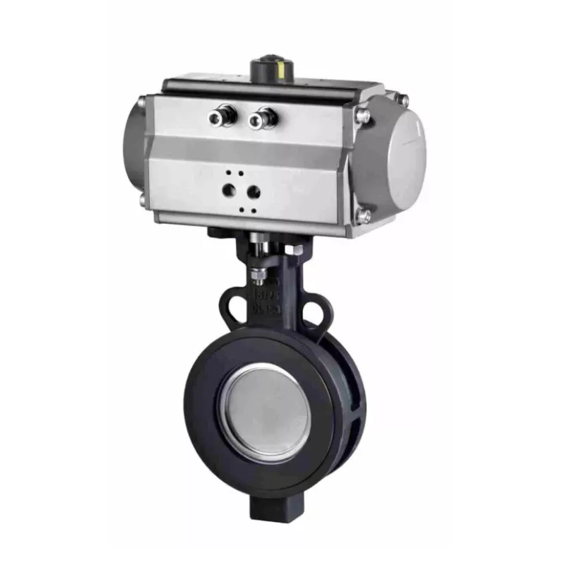
The seat is the main sealing element in many concentric butterfly valves. Repeated opening and closing gradually compresses and wears the elastomer. High temperature can harden it, while incompatible chemicals may cause swelling, softening, cracking, or loss of elasticity. Once the seat can no longer conform evenly around the disc edge, internal leakage through the closed valve begins.
Seat damage is not always caused by age. Over-torquing the valve, storing it in the wrong position, or forcing the disc through accumulated solids can permanently deform the sealing surface. Before installing a replacement seat, technicians should identify why the original one failed.
The disc edge must remain smooth and correctly aligned with the seat. Scoring, pitting, corrosion, cavitation, or abrasive erosion creates small channels through which fluid can pass. A bent or worn shaft may also shift the disc away from its intended centerline, producing uneven seat compression.
If one side of the seat shows much more wear than the other, the problem may be disc misalignment, pipe stress, bearing wear, or actuator misalignment, rather than normal seat deterioration.
Weld slag, rust scale, sediment, fibers, crystals, or process solids may become trapped at the sealing interface. Even a small hard particle can prevent full closure and create a continuous leak path. This problem is especially common after new pipeline construction, maintenance work, or an upstream equipment failure.
A valve may appear closed on the control system while the disc is still slightly open. Incorrect limit-switch settings, worn gearboxes, weak pneumatic supply, actuator undersizing, or positioner calibration errors can prevent the disc from reaching its full seating position.
Too little torque causes incomplete closure, but excessive torque is also harmful. Over-torquing can damage the seat, twist the shaft, or shorten the service life of the actuator and gearbox. The actuator must be sized according to valve diameter, pressure differential, media characteristics, seat material, and operating frequency.
Uneven flange tightening, incorrect gasket selection, flange misalignment, and unsupported pipe loads can distort the valve body. The disc may then rub against the pipe or compress the seat unevenly. Improper installation can make a new butterfly valve leak immediately, even when every valve component is undamaged.
Butterfly valve leakage generally appears in three locations: through the closed valve, around the stem, or at the flange connections. Locating the leak correctly is essential because each location requires a different repair.
| Leakage location | Typical symptoms | Common causes | Initial checks |
|---|---|---|---|
| Through the closed valve | Downstream pressure rises or flow continues after closure | Worn seat, damaged disc, trapped debris, incomplete disc travel | Confirm valve position, inspect actuator travel, flush the line, test seat tightness |
| Around the stem or neck | Fluid appears below the actuator or around the shaft | Worn packing, damaged O-rings, shaft scoring, excessive cycling | Inspect packing area, check shaft surface, confirm operating pressure and temperature |
| Between valve and flange | External dripping or spraying at the pipeline joint | Uneven bolts, damaged gasket, pipe misalignment, incorrect flange spacing | Check bolt pattern, flange alignment, gasket condition, and pipe support |
| Actuator or gearbox connection | Valve cannot fully close or position changes unexpectedly | Loose coupling, worn gearbox, air-pressure loss, faulty positioner | Check coupling, air supply, solenoid, limit switches, and closing torque |

Internal leakage occurs when media passes the disc even though the valve is commanded closed. This is often called seat leakage or valve passing. It may not be visible outside the pipeline, so operators usually notice it through downstream pressure, unexpected flow, product mixing, or difficulty isolating equipment.
Stem leakage occurs when process media moves along the shaft and escapes through the packing or O-ring system. The surrounding actuator bracket may show moisture, residue, crystallization, or corrosion. This failure should not be ignored because the leaking media can damage the actuator and create an external safety hazard.
Flange leakage occurs outside the valve at the connection with the pipeline. It may be caused by a damaged gasket, incompatible flange design, poor bolt-tightening sequence, or excessive pipe stress. Tightening one bolt aggressively is not a reliable solution; it can increase body distortion and make the leakage worse.
Some operating environments place much greater stress on seats, discs, shafts, packing, and actuators. Valve selection and maintenance frequency should therefore reflect the application rather than relying only on nominal pipe size.
In Wastewater & Slurry Systems, suspended solids, fibers, grit, and sediment can lodge between the disc and seat. Solids may also accumulate around the shaft area and restrict disc movement. Frequent flushing, suitable seat geometry, and correct installation orientation can reduce the risk of debris-related seat leakage.
In Chemical Processing Systems, chemical compatibility is critical. An elastomer that performs well in water may swell, harden, or crack when exposed to solvents, acids, alkalis, or hydrocarbons. The valve body, disc, stem, seat, and seals must all be checked against the actual media concentration and temperature. Material incompatibility can cause rapid leakage even when the valve has completed only a small number of cycles.
Steam & High-Temperature Systems expose sealing materials to thermal expansion, heat aging, and repeated temperature cycles. Standard soft seats may lose elasticity or exceed their rated temperature. Flange bolts can also loosen gradually as the piping repeatedly heats and cools. High-temperature applications may require a high-performance or metal-seated butterfly valve rather than a general-purpose resilient-seated design.
In Mining, Slurry & Abrasive Media Systems, hard particles continuously attack the disc edge and seat. High flow velocity increases erosion, while partially open operation concentrates wear along specific areas of the disc. If a standard valve repeatedly develops scoring or pitting, changing only the seat will not provide a durable solution. The system may require a more wear-resistant disc, lining, seat, or valve design.
High-Frequency Automated Production Lines may cycle a butterfly valve thousands of times within a relatively short period. Frequent actuation accelerates packing fatigue, bearing wear, seat compression, and coupling looseness. In these systems, maintenance should be based on cycle count and actuator diagnostics, not only on calendar intervals. Stable pneumatic supply and accurate position feedback are equally important.
Repair should begin only after the pipeline has been safely isolated. A methodical process prevents technicians from replacing the wrong component or returning an unsafe valve to service.
Follow the facility’s lockout/tagout procedure, stop the flow, release trapped pressure, drain hazardous media, and verify a zero-energy condition. Never loosen flange bolts or remove an actuator while the valve is pressurized. Review the safety data for the process fluid and use the required protective equipment.
Determine whether the problem is internal seat leakage, stem leakage, flange leakage, or incomplete actuator closure. Check upstream and downstream pressure, inspect the stem area, examine flange joints, and verify the commanded and actual disc positions.
If the valve is automated, check air pressure, solenoid operation, actuator coupling, positioner feedback, and limit-switch settings before dismantling the valve. A calibration problem can often imitate seat damage.
Remove the valve in accordance with the manufacturer’s instructions. Inspect the seat for hardening, swelling, cuts, grooves, permanent compression, or embedded debris. Examine the disc edge for corrosion, cavitation, pitting, and abrasive scoring. Check the shaft, bearings, packing, O-rings, and body for wear or distortion.
Asymmetrical wear deserves special attention. It may indicate pipe misalignment, a bent shaft, worn bearings, or an actuator mounted off-center. Replacing the seat without correcting this condition will lead to another leak.
Remove all deposits from the body cavity and sealing surfaces without scratching the metal. Replace damaged seats, packing, O-rings, or bearings with parts that match the valve design and process media. Use only a material-compatible lubricant where the manufacturer permits lubrication. Petroleum-based products should not be applied to elastomers that are incompatible with them.
Minor flange leaks may be corrected by replacing the gasket, realigning the pipe, and tightening bolts in the recommended cross pattern. Do not attempt to compensate for badly misaligned piping by applying excessive bolt force.
Reinstall the disc, shaft, seat, and actuator according to the specified orientation and torque values. Confirm that the disc moves freely through its full travel without contacting the pipe. Recalibrate the open and closed limits, then verify that the actuator provides sufficient closing torque without overloading the stem or seat.
Perform the required seat-tightness and shell-integrity tests in accordance with the valve manufacturer’s procedure and the applicable project standard. Hold the test pressure for the specified time, check the stem and flange areas, and record the result. Return the valve to operation gradually while watching for pressure instability, abnormal noise, or renewed leakage.
The most effective way to control leakage is to address valve selection, installation, operation, and maintenance as one connected process.
First, select body, disc, stem, seat, and seal materials according to the actual media, concentration, temperature, pressure, solids content, and cleaning chemicals. A valve selected only by diameter and pressure class may still fail quickly if the seat material is unsuitable.
Second, keep the pipeline clean during construction and commissioning. Flush out welding debris, scale, and foreign objects before operating the valve. Confirm that flange faces are parallel, pipe supports are adequate, and the disc has enough clearance to rotate without hitting the pipe.
Third, size and calibrate the actuator correctly. Check pneumatic pressure at the actuator under real operating demand, not only when the line is idle. Inspect solenoids, regulators, couplings, positioners, and limit switches regularly. Stable actuator torque and accurate travel settings are essential for consistent shutoff.
Fourth, build preventive maintenance around process severity. Clean-water service may require only periodic inspection, while abrasive slurry, aggressive chemicals, steam, or rapid cycling may require shorter intervals. Recommended tasks include:
Inspecting the stem and flange areas for early signs of leakage.
Exercising valves that remain in one position for long periods.
Recording operating temperature, pressure, and cycle count.
Checking actuator travel and air-supply stability.
Listening for cavitation, vibration, or abnormal throttling noise.
Tracking seat, packing, and actuator replacement history.
Investigating repeated failures instead of treating them as unrelated events.
A computerized maintenance management system can help identify valves that consume excessive parts or labor. Failure history is often the clearest indication that the valve design or material specification no longer suits the application.
Repair is reasonable when the body, disc, and shaft remain structurally sound and the leak is limited to a replaceable seat, packing set, gasket, or actuator adjustment. Replacement becomes more economical when the damage affects major metal components, the valve repeatedly fails, or the application exceeds the original design.
| Evaluation factor | Repair may be suitable | Replacement or upgrade is recommended |
| Damage location | Wear is limited to the seat, packing, O-rings, or gasket | Disc edge is deeply scored, shaft is bent, or body is corroded or distorted |
| Failure history | First leakage event after a long service period | Leakage returns repeatedly after repair |
| Process media | Clean, compatible, low-abrasion fluid | Corrosive chemicals, abrasive slurry, steam, or severe solids |
| Operating conditions | Pressure and temperature remain within the original rating | Thermal spikes, pressure surges, cavitation, or vibration exceed design conditions |
| Parts and downtime | Correct replacement parts are available and repair is quick | Parts are obsolete or repair downtime costs more than a replacement |
| Actuation | Calibration or a serviceable actuator component caused the problem | Gearbox, shaft, coupling, and actuator show extensive wear |
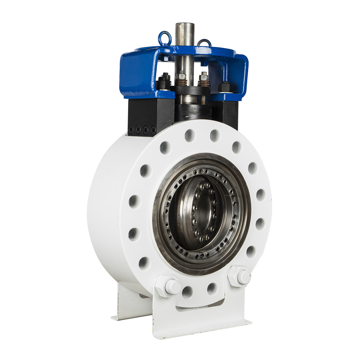
Replace the valve if the body has lost structural integrity, the disc can no longer form a continuous sealing line, the shaft is permanently damaged, or the valve cannot pass the required pressure test after repair. Repeated seat failures within a short period usually indicate that another design is needed.
For high temperature, abrasive media, high pressure differentials, or frequent cycling, an upgrade to a high-performance butterfly valve or an application-specific sealing design may provide a lower total cost of ownership. The decision should consider purchase price, labor, replacement-part availability, downtime, product loss, safety exposure, and expected service life—not just the cost of one repair kit.
Close the valve fully and monitor the downstream side. Continued downstream flow or a gradual pressure increase indicates internal passing. Before assuming the seat is damaged, confirm the disc position, actuator travel, and presence of trapped debris.
Stem leakage is commonly caused by worn packing, damaged O-rings, shaft scoring, excessive cycling, chemical incompatibility, or thermal aging. Inspect both the sealing elements and the shaft surface because new packing may not seal properly against a badly scored stem.
External checks, actuator calibration, air-supply correction, and some packing adjustments may be completed in place if the manufacturer permits them. However, seat, disc, shaft, bearing, and internal seal replacement normally requires isolation, depressurization, and valve removal.
It may help if bolts have loosened evenly, but uncontrolled tightening can distort the body or damage the gasket. Check flange alignment, gasket condition, pipe support, and the specified tightening sequence first. Never use excessive bolt torque to pull misaligned piping into position.
Intermittent leakage often points to fluctuating pneumatic pressure, a sticking solenoid, a loose coupling, inaccurate positioner feedback, or changing thermal conditions. Record air pressure and disc position during the actual leakage event to identify the variable.
The interval depends on media, pressure, temperature, cycle frequency, and the consequences of failure. High-frequency automated service and abrasive or corrosive applications need more frequent inspection than clean-water isolation. Use risk, operating history, and cycle count to establish the schedule.
Only if normal seat wear is the true cause. If the new seat fails again, inspect the disc edge, shaft alignment, bearings, actuator torque, piping alignment, velocity, temperature, and media compatibility. Repeated leakage is evidence of an unresolved system or selection problem, not simply another worn consumable.


