

Views: 0 Author: Site Editor Publish Time: 2026-05-08 Origin: Site


Industrial steam pipelines operate under extreme working conditions featuring high temperature, high pressure, pressure differential fluctuations and two-phase unstable flow, which puts forward dual core requirements for pipeline valves: precise and repeatable flow regulation control and absolute zero-leakage isolation. This article comprehensively elaborates on the technical advantages of globe valves as the optimal solution for industrial steam pipeline systems, covering their throttling mechanism, metal sealing performance, pressure drop adaptation and material adaptability.
1.The Engineering Case for Globe Valves in Steam Pipelines
2.Critical Specifications for a Steam Globe Valve
3.Automation and Process Integration
4.Evaluating Globe Valves Against Alternative Valve Types
5.Total Cost of Ownership (TCO) and ROI Drivers
6.Implementation Risks and Sizing Considerations
7.Conclusion
8.FAQ
Steam pipelines demand a valve that simultaneously delivers precise flow modulation and absolute leak-tight isolation — under extreme temperatures, high pressure differentials, and two-phase flow conditions. Gate valves erode when throttled; soft-seated ball valves deform under high-pressure steam. Globe valves address both failure modes through a Z-shaped flow path and perpendicular sealing mechanism that eliminate wire-drawing erosion and maintain seating integrity through severe thermal cycling.
Four attributes define their engineering advantage in steam service:
Superior throttling control — perpendicular disc travel prevents the localized high-velocity erosion that destroys gate and ball valves during partial-open operation.
Metal-to-metal seating integrity — hardened trim (e.g., Stellite) sustains ANSI/FCI 70-2 Class IV–VI shut-off ratings even after prolonged thermal cycling.
Specification flexibility — material and connection options, from carbon steel flanged bodies to stainless steel flanged globe valves, match varying steam grades including saturated and superheated service.
Lower lifecycle cost — higher initial pressure drop and procurement cost are offset by extended MTBF, in-line reparability, and actuator integration.
Valve stem travel directly dictates the available flow area within the valve body. You need a predictable response to control thermal systems accurately. Globe valves offer an exceptional correlation between stem position and flow capacity. Unlike quarter-turn valves that open rapidly and unevenly, they provide granular control over the media. You can swap internal plug designs to achieve specific flow characteristics based on process requirements. Understanding how to select the proper trim involves specific technical steps:
Analyze the upstream pressure and maximum required steam load.
Determine the required flow characteristic curve (linear vs. equal percentage) dictated by the downstream equipment.
Specify the precise trim material hardness required to handle the calculated pressure drop.
Plug Design
Flow Characteristic
Primary Industrial Application
Parabolic Plug | Linear | Straightforward level control and steady steam distribution headers. |
V-Port Plug | Equal Percentage | Heat exchangers requiring highly precise low-flow regulation to prevent thermal shock. |
Flat Plug | Quick Opening | Fast isolation and minimal throttling applications. |
Specify a parabolic plug when your system requires linear flow characteristics. This design ensures that the flow capacity increases linearly with stem travel, making it ideal for continuous steam distribution. Alternatively, use a V-port plug for equal percentage control. A V-port design heavily restricts flow during the initial opening stages. It allows for highly precise regulation of steam pressure and temperature feeding into sensitive downstream heat exchangers. This control mechanism prevents sudden thermal shocks and ensures highly stable heat transfer rates.
The perpendicular closure mechanism represents a major mechanical advantage in fluid control. In this design, the disc moves parallel to the flow direction as it approaches the seat. It makes physical contact only at the exact moment of closure. This direct, top-down seating avoids the aggressive sliding friction that rapidly degrades the sealing surfaces of gate valves.
Throttling steam inherently creates high-velocity localized flow. When a valve is partially open, wet steam accelerates across the seat, causing a destructive phenomenon known as wire drawing. This kinetic erosion cuts deep, unrepairable channels into soft metals. Manufacturers mitigate wire drawing by utilizing hardened trim materials. Fusing Stellite or similar cobalt-chromium alloys to the seating surfaces drastically increases hardness. Combining this advanced metallurgy with optimized seating angles ensures the valve maintains a tight seal even after years of continuous flow modulation.
Engineers often point to the high pressure drop, or lower Flow Coefficient (Cv), as a disadvantage. The complex internal Z-shaped flow path forces the steam to change direction multiple times. This internal turbulence absorbs kinetic energy and reduces downstream pressure. In steam regulation, we do not view this as a negative attribute.
This pressure drop serves as a necessary physical trade-off for achieving precise pressure reduction. By absorbing energy within its robust body, the valve manages physical phase changes safely. Flashing and cavitation occur when the pressure drops below the vapor pressure of the fluid. The heavy wall thickness and robust internal trim contain these destructive forces, preventing acoustic vibration and mechanical fatigue from transferring to the surrounding, thinner-walled piping infrastructure.
Connection type dictates installation safety and long-term maintenance efficiency. You should select a Flanged Globe Valve for mid-to-large bore steam lines over threaded or socket-weld options. Threaded connections become notoriously difficult to disassemble after enduring thousands of thermal cycles. They often seize entirely, requiring destructive removal methods.
Flanged connections, specifically ASME B16.5 rated flanges, allow for predictable torque specifications. Maintenance crews can torque bolts to exact tolerances, ensuring an even, leak-proof seal across the gasket. Flanged joints handle the severe thermal expansion of steam pipelines effectively. When technicians need to service the unit, they follow strict maintenance protocols without hot-work permits:
Verify complete system depressurization via block and bleed valves.
Loosen the flange bolts gradually in an alternating star pattern.
Inspect the flange faces for any signs of steam cutting or pitting.
Install a new spiral wound gasket and secure the valve body back into the line.
Utility steam applications generally operate within well-defined parameters. For standard boiler distribution, carbon steel bodies like ASTM A216 WCB or WCC perform exceptionally well. They provide high tensile strength and handle temperatures up to 425°C (800°F) safely and economically.
Specific process requirements mandate upgrading to a Stainless Steel Flanged Globe Valve. Clean steam applications in pharmaceutical manufacturing, food processing, or semiconductor fabrication require ASTM A351 CF8M (316 stainless steel) to prevent iron contamination. You must also specify stainless steel in high-condensate zones. Carbon dioxide dissolved in cooling condensate forms carbonic acid. This acidic mixture rapidly corrodes standard carbon steel. Stainless steel provides the necessary corrosion resistance, ensuring longevity in poorly drained sections of the piping network.
Standard bolted bonnets become a severe safety liability as steam pressure increases. The internal pressure pushes against the bonnet, stretching the bolts and potentially causing the gasket to leak. For high-pressure and superheated applications exceeding ASME Class 600, you must transition to pressure seal bonnets. Specifying a proper High Pressure Globe Valve is a non-negotiable safety requirement for power generation and heavy industrial boilers.
Pressure seal designs flip the mechanical physics of the valve. They utilize the internal system pressure to increase the sealing force. As steam pressure rises, it actively pushes the internal bonnet assembly upward against a metallic gasket. The higher the pressure, the tighter the seal becomes. This design prevents blowouts in superheated distribution networks, ensuring strict compliance with ASME B16.34 standards and protecting downstream equipment.
Fugitive emissions represent a hidden financial cost and a severe safety danger. Standard graphite packing relies on physical compression from a gland nut to seal around the moving stem. Over time, thermal cycling and friction cause this packing to consolidate and wear. Live steam inevitably escapes, costing the facility money in lost thermal energy and creating immediate burn hazards for operators on the floor.
Bellows seal designs serve as an upgrade for absolute zero-leakage performance. This technology welds a flexible metallic accordion-like cylinder directly between the valve stem and the bonnet, creating an impenetrable physical barrier. They completely eliminate the need for periodic gland packing tightening and protect personnel from live steam exposure in hazardous or hard-to-reach locations.
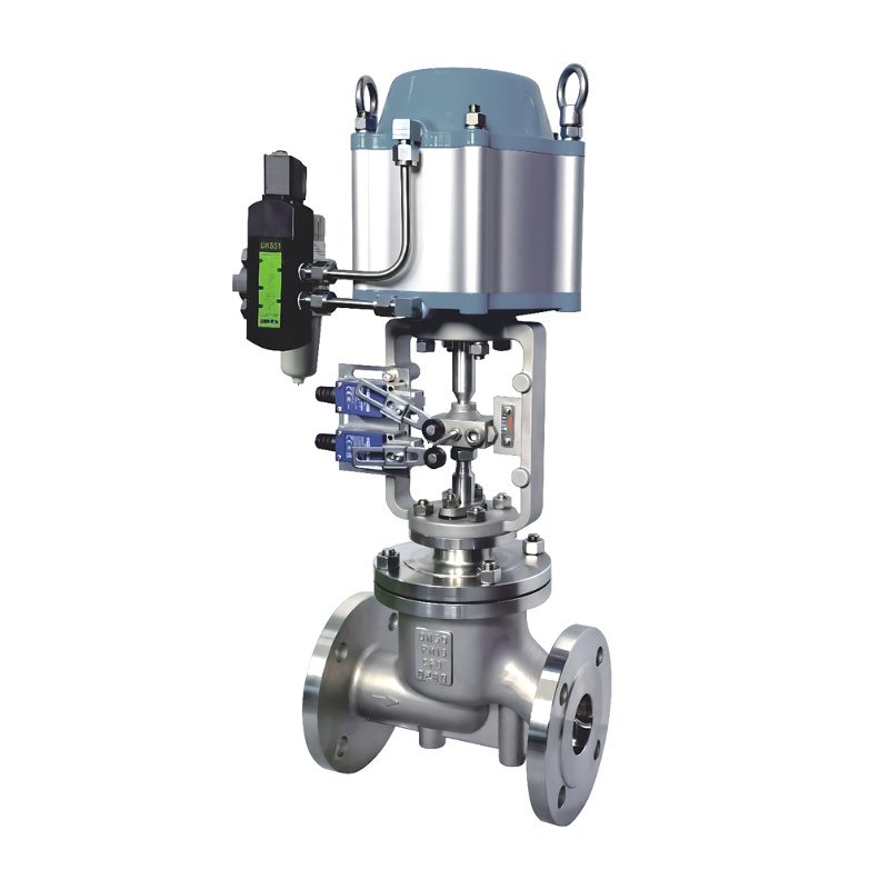
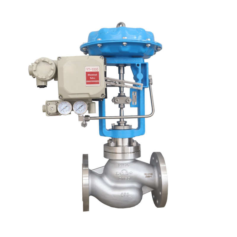
Modern process control requires transitioning from manual handwheel operation to automated systems. Pneumatic or electric actuators take control of plant loops, ensuring instantaneous response to changing process variables. However, actuating a steam valve requires careful engineering.
You must specify high-thrust actuators. The dynamic forces of high-pressure steam constantly push against the internal plug. The actuator must possess enough reserve thrust to overcome fluid pressure, stem packing friction, and the mechanical resistance of seating surfaces. Pneumatic diaphragm actuators remain the industry standard due to fail-safe spring mechanisms. If instrument air fails, the heavy internal spring mechanically forces the valve into a predetermined safe position, usually fail-closed for steam isolation.
Mounting a simple actuator is no longer sufficient for modern facilities. Integrating Digital Valve Controllers (DVCs), or smart positioners, with throttling valves unlocks diagnostic capabilities. A smart positioner continuously monitors the exact position of the stem and compares it to the 4-20mA control signal.
These devices track critical telemetry, including stem friction, breakaway torque, and stroke latency. As internal trim wears or packing tightens, stem friction increases. The DVC logs these subtle changes and alerts operators to degrading performance long before an actual mechanical failure occurs. This predictive maintenance approach allows technicians to schedule repairs during planned outages, entirely avoiding expensive unplanned steam pipeline shutdowns.
Choosing the correct valve requires understanding exactly how different mechanical designs react to steam. The table below outlines the realities of various valve types under industrial steam conditions.
Valve Type
Primary Function
Throttling Capability in Steam
Wear Resistance & Failure Modes
Globe Valve | Modulation & Isolation | Excellent (Linear or Equal Percentage) | High. Resists wire drawing. Metal-to-metal seals endure thermal cycling effectively. |
Gate Valve | Isolation (On/Off) Only | Extremely Poor | Low if throttled. Suffers severe seat erosion, chattering, and stem fatigue. |
Ball Valve (Soft Seat) | Fast Isolation | Poor | Very Low. PTFE/elastomer seats melt or extrude out of place under high pressure. |
Butterfly Valve (Metal Seat) | Large Bore Isolation | Moderate | Prone to thermal binding. Expensive to manufacture with zero-leakage tolerances. |
Operators frequently attempt to use gate valves for flow modulation to lower procurement costs. This is a severe engineering error. Gate valves use a flat wedge that moves perpendicular to the flow. When partially open, high-velocity steam aggressively batters the bottom edge of the wedge.
The immediate outcome is rapid seat erosion and violent mechanical chattering. The wedge bounces against the internal guides, eventually fatiguing the stem connection. The definitive verdict remains clear: Gate valves are strictly for On/Off isolation. You must specify globe valves whenever process flow modulation or pressure reduction is necessary.
The temptation to use quarter-turn ball or butterfly valves is high. They actuate faster and generally carry a lower initial capital cost. Steam destroys typical quarter-turn materials rapidly. Standard ball valves rely on PTFE or elastomer seats. High-pressure steam degrades, melts, or extrudes these soft materials, leading to massive internal leakage and complete failure.
Upgrading to metal-seated rotary valves solves the melting issue but introduces new problems. Metal-seated ball and butterfly valves are extremely expensive and highly prone to thermal binding. Thermal binding occurs when the rapid expansion of the internal ball seizes against the metal seat, rendering the valve completely immovable. When you specify a proper Steam Globe Valve, you bypass these mechanical vulnerabilities entirely. They offer a reliable metal-to-metal seal with superior linear control and absolute immunity to thermal binding.
When reviewing quotes, you notice the higher initial capital expenditure compared to equivalent-sized gate or butterfly valves. The complex internal casting and heavier wall thicknesses demand more raw material and machining time. When we evaluate a steam component purely on purchase price, we ignore the financial reality of operations.
You map the return on investment through risk mitigation. A single unplanned steam outage caused by a failed gate valve costs tens of thousands of dollars in lost production. Furthermore, these designs require significantly fewer replacements over a twenty-year plant lifecycle. Investing upfront in robust control mechanisms directly lowers long-term operational costs.
A leaking steam valve literally vents money into the atmosphere. Passing steam through a degraded, closed valve wastes massive amounts of thermal energy. Plant energy audits routinely uncover failing isolation valves that force boilers to consume excess natural gas just to maintain header pressure. You quantify this financial cost through a strict auditing process:
Measure the internal steam line pressure feeding the leaking valve.
Estimate the orifice size of the internal leak path caused by wire drawing.
Apply Napier's equation for steam flow to calculate pounds per hour of lost steam.
Multiply the total lost steam volume by the unit cost of boiler fuel to reveal the true cost of the leak.
The reliable, tight shut-off provided by a globe valve stops this invisible bleed. Upgrading to high-quality components directly improves plant thermal efficiency and yields a measurable reduction in boiler fuel consumption.
Maintenance accessibility is a primary driver of TCO. When a unit fails, cutting it out of heavy-schedule piping requires welders, x-ray inspections, and extensive downtime. The top-entry design offers a distinct maintenance advantage.
Maintenance crews can isolate the line, unbolt the bonnet, and pull the entire trim assembly out through the top. The body remains fully welded or flanged into the pipeline. Technicians replace stem packing, machine the seating surfaces, or swap out a damaged plug directly on the catwalk. This in-line reparability drastically reduces turnaround times during plant shutdowns.
The most common implementation error involves specifying a valve based purely on nominal pipeline size rather than the actual steam flow rate. An 8-inch pipe does not automatically require an 8-inch control valve. An oversized unit operates too close to the seat, hovering at 5% to 10% open.
This causes hunting, where the plug rapidly bounces near the seat attempting to find stability. Hunting causes premature wear, poor temperature control, and mechanical fatigue. You mitigate this by utilizing strict sizing calculations:
Calculate the maximum, normal, and minimum required steam loads for the process.
Determine the specific inlet pressure and required pressure drop across the valve.
Utilize flow coefficient formulas to determine the exact Cv requirement.
Select a valve size where the normal flow condition falls between 50% and 70% of the total stem travel.
These valves are highly directional. Installing them backward severely compromises safety and control. You choose between "Flow Under the Seat" (F-to-O) and "Flow Over the Seat" (O-to-F) orientations based on the specific application.
Flow Under the Seat is the standard for steam throttling. Fluid pressure pushes up against the plug, making it easier for actuators to open against pressure and acting as a failsafe mechanism—if the stem snaps, the fluid pressure pushes the valve open. Flow Over the Seat is mandated for severe high-pressure isolation. Steam pressure pushes down on top of the plug, utilizing process pressure to force the seal tightly closed for absolute shut-off.
Steam lines constantly generate condensate as heat transfers to the environment. If a valve remains closed, condensate pools heavily behind it. When it opens suddenly, high-velocity steam picks up this wall of water and slams it into internals or piping elbows.
This phenomenon, known as water hammer, physically shatters castings and destroys internal trim. You mitigate this through proper piping design. Position thermodynamic steam traps directly upstream to drain pooling water. Utilize small bypass lines around the main unit to allow gradual pipeline warm-up and pressure equalization before opening the primary line.
Maintaining live steam lines involves severe, life-threatening hazards. Attempting top-entry maintenance without absolute certainty of isolation is extremely dangerous.
Outline the strict implementation of Double Block and Bleed (DBB) configurations upstream. This protocol involves closing two isolation valves in series and opening a bleed valve between them to vent passing steam safely. Guarantee complete depressurization and allow adequate cooling time before technicians loosen a single bonnet bolt.
Globe valves serve as the definitive standard for regulating flow and pressure in modern steam networks. No other design balances the requirement for high-precision throttling with robust, leak-tight shut-off. By leveraging their mechanical advantages, you protect your infrastructure from premature failure and thermal energy losses.
Take the following actions to ensure optimal performance and safety in your facility:
Audit your current steam distribution network to identify any gate or ball valves improperly installed for throttling applications.
Calculate precise flow coefficient (Cv) requirements based on maximum and minimum steam loads before procuring replacement components.
Review maintenance logs to isolate problem areas with high repacking frequencies and upgrade those locations to bellows seal designs.
Consult with a qualified engineering firm to verify exact material compatibility and pressure class ratings for your specific steam parameters.
A: Yes. They are uniquely engineered to perform both functions reliably. The internal geometry provides precise flow modulation without the rapid seat erosion typical of gate valves. Their top-down, metal-to-metal seating mechanism also guarantees strict shut-off capabilities when fully closed, securely isolating the pipeline.
A: Flanged connections allow for rapid, safe in-line maintenance. Technicians can remove the valve body without cutting pipes or securing hot-work permits. Flanges handle severe thermal expansion better than rigid threaded joints and permit precise bolt torque applications, significantly reducing the risk of hazardous steam leaks.
A: Wire drawing is severe metal erosion caused by high-velocity wet steam ripping across a partially open valve seat. Manufacturers prevent this destructive channel-cutting by applying hardened metal alloys, such as Stellite, to the internal trim and optimizing the plug geometry to direct kinetic energy away from sealing surfaces.
A: Pressure class selection depends entirely on the maximum operating pressure and peak temperature of the steam system. Standard bolted bonnets safely handle up to ASME Class 600. For high-pressure superheated lines (Class 900, 1500, 2500), ASME B16.34 standards mandate pressure seal bonnets to prevent catastrophic blowout failures.
A: No. Standard carbon steel bodies (WCB/WCC) are highly effective and economical for basic utility steam distribution. You only need to specify stainless steel (CF8M) for clean steam processes, sanitary environments, or piping sections prone to corrosive carbonic acid accumulation from high condensate levels.
A: The standard orientation is "Flow Under the Seat" (F-to-O) for throttling applications. Fluid pressure pushes up against the plug, making actuation easier against line pressure and serving as a failsafe to open if the stem breaks. "Flow Over the Seat" is reserved exclusively for severe high-pressure isolation.
A: You must specify a bellows seal when zero fugitive emissions are mandatory for safety or environmental compliance. They use a welded metallic accordion barrier instead of compressed graphite rings, completely eliminating external steam leakage and permanently removing the need for routine packing gland maintenance.


